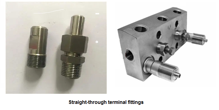
The input signal pressure of the Fuji transmitter is generally introduced in three ways: through the straight-through terminal joint, through the waist flange and through the valve manifold.

1.1 Via straight-through terminal fittings
The straight-through terminal connector is shown in Figure 5. The connector body has external threads, which screw into the pressure port of the transmitter. Threads are available in various specifications to suit the needs of different types of transmitters. The nozzle is welded with the pressure guiding tube, and it also has various specifications to match the pressure guiding tube with different diameters and wall thicknesses. When disassembling, just unscrew the outer nut, the Fuji transmitter and the pressure guiding tube can be separated.
1.2 Through the oval flange
A waist flange is a small flange, shaped like a waist, sometimes called an oval flange. It is fixed on the pressure guide port of the Fuji transmitter with two screws. One end of the flange is connected with the transmitter, and the other end has an internal thread interface. The straight-through terminal joint or the pressure guide pipe is screwed on this interface.
1.3 Connecting through the valve manifold
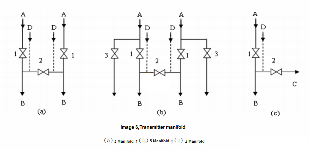
Fuji transmitter valve group has three valve group, two valve group, five valve group and so on. The introduction of the input pressure of the transmitter adopts a three-valve group. The connection between the differential pressure transmitter and the pressure guiding pipe can also be through the three-valve manifold. The integrated three-valve group consists of two pressure-inducing valves 1 and a balance valve 2. The integrated three-valve manifold is more compact and easier to install than the separate three-valve. The five-valve group is based on the three-valve group with two additional blowdown valves 3 (empty). During normal operation, close the two sets of blowdown valves and balance valves; when the instrument is at zero position, cut off the high and low pressure valves and open the balance valve. Two valve groups are generally used in pressure transmitters, through which the process pressure is connected with the pressure guide port of the transmitter, and its working principle is shown in Figure 6(c). Among them, A is connected to the process conduit, B is connected to the pressure guide port of the pressure transmitter, C is used for blowdown or purging, and D is the calibration port. Two-valve manifolds can sometimes also be used with differential pressure transmitters.

2. Commonly used auxiliary containers
Commonly used auxiliary vessels are condenser, isolator, gas collector and settler. When the measured fluid is steam, it is transmitted to the transmitter in the form of condensed water in the pressure guiding pipe. In order to keep the liquid level in the two pressure guiding pipes unchanged, a condenser is often installed on the pressure guiding pipe near the throttling device. In addition, in order to prevent the precipitation in the liquid from clogging the conduit, a settler and a sewage valve are installed at the lowest part of the conduit to discharge the dirt regularly. The gas collector and the settler are an empty tank, and the volume can be designed as large as possible to prolong the period of degassing and sewage discharge.
