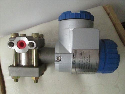
FUJI FKG Fuji differential pressure transmitter fault

These are two kinds of FUJI differential pressure transmitter faults that I have encountered recently. The process is a bit bumpy, and I only talk about the phenomenon and conclusion.
First Project:
Phenomenon: 475 communication shows that the current is 4mA, and the differential pressure is 0kPa (the range setting has no migration, 0~1000kPa, the meter display is also 0%), everything is normal. However, the loop current is tested to be 6mA, which leads to an extra 2mA corresponding to 125kPa in the DCS display. LOOP TEST with 475, 4mA, 8mA, 12mA, 16mA, 20mA, the measured loop current is about 2mA more than the corresponding value. +2.1mA, 16+1.9mA, 20+1.6mA.
Solution: After inspection, it was found that there was no problem with the FKG transmitter, and the current value was found to be too high by measuring the current with a multimeter. After correcting the current problem, there is no need to change the module
Second Project:
FUJI FKC33V5 differential pressure transmitter high and low pressure guide pipes are reversed
There is a flow measurement system, the primary element is an orifice plate, and the differential pressure transmitter is a measuring instrument. When the system is put into operation, the output of the differential pressure transmitter not only does not rise, but runs below zero.
Analysis and judgment: When the flow measurement system matched with the throttle orifice plate and the differential pressure transmitter is put into operation, the output of the instrument runs below zero, which may have the following reasons:
(1) The high pressure conduit of the transmitter is blocked or leaked
(2) The high and low pressure conduits of the transmitter are reversely connected;
(3) The flow direction of the medium in the process pipeline is opposite;
(4) The transmitter is faulty
After inspection, the FKC33V5 transmitter is good, the output can change with the change of the differential pressure signal, and the pressure guiding pipe is not blocked or leaked, but the high and low pressure guiding pipes are connected reversely (the medium flows in the opposite direction, which can also be regarded as a guide pipe). the pressure pipe is reversed).
Handling measures For smart transmitters, there are two handling measures:
(1) Change the relative position between the detection part and the transmission part and the interface of the pressure guiding pipe. The KCX-A/C series transmitter has two high pressure guide ports and two low pressure guide ports, and they are interchangeable. If the front guide port is connected to the pressure guiding tube, the latter guide port is connected to the drain plug. Therefore, just turn the relative position of the detection part and the transmission part by 180°, and change the pressure guide port to the other one.
When changing the relative position of the two parts for detection and transmission, first unplug the connector of the flat cable in the transmission part, and then remove the two external hexagon socket head cap screws for rotation. it pulls off;
(2) Change the position of the positive and negative action tabs. For the FCX-A/C transmitter, there is also a negative effect, that is, the differential pressure model increases and the instrument output decreases. The method of selecting positive and negative action is to change the position of the contact piece. If the pressure guiding tube is connected in reverse, just change the contact piece in the table from the positive action "NOR" position to the reverse action "REV" position.
When changing the position of the positive and negative action tabs, first remove the watch cover with the display window, loosen the two screws that fix the display board, remove the display board, you can see the tabs on the circuit board, and lightly remove it by hand. Gently unplug and insert into the desired location.


