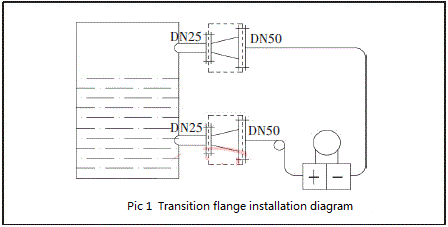
As shown in Figure 1, the diameter of the on-site process flange is DN25. A flange assembly that can convert the diameter of the flange is added between the DN50 pressure-taking flange and the DN25 process flange. The dotted frame in the figure is from right to left. The purpose of converting the flange diameter from DN50 to DN25 is achieved. In the design and manufacture of the instrument, it is customary to call the part of the flange assembly between the pressure-taking flange and the process flange as the transition flange, here is the DN50-DN25 transition flange.
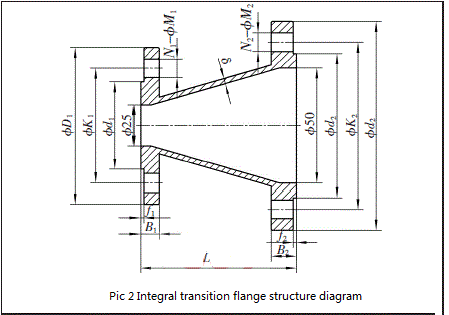
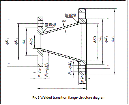
 When designing the transition flange, in theory, it should be treated as a whole, as shown in Figure 2. However, considering many factors such as the feasibility of the machining process of the parts, material and labor costs, in the actual design, two flanges and a section of bell mouth are mostly welded. Here is "one large flange (DN50) and one small flange (DN25) plus bell mouth", as shown in Figure 3, the weld design of the joint is selected and determined according to the process #high working pressure, which can also achieve the strength of the overall design requirements, both to meet the process requirements and to facilitate production. In the figure, the dimensions of D, K, d, f, B, δ and N-M belong to the standard design, and the corresponding values are designed and selected according to the different nominal pressure values of the flanges. The length of L is determined according to the effective length of the bolts on both sides. The premise is that the bolts on both sides do not interfere with each other, which is convenient for installation and compact.
2.2 DN25 adapter flange assembly
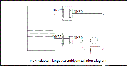
The adapter flange is shown in the double-dot-dash box in Figure 4. It is similar in type to the transition flange. In order to achieve the miniaturization of the transition flange as much as possible, shou first optimized the pressure-taking flange of the remote transmitter. Design, so that the pressure-taking flange has the dual function of taking pressure and connecting, and then design the adapter flange on this basis.
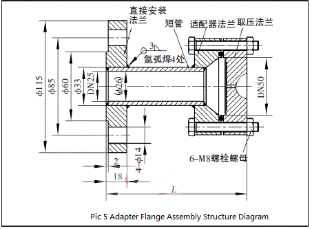
Taking the transition from DN50 PN16 to DN25 PN16, which is the industry standard of the Ministry of Chemical Industry, as an example, as shown in Figure 5, shou first matches the pressure-taking flange and the adapter flange to ensure a reliable connection between the two. Secondly, the diameter of the right side of the adapter flange is DN50, and the diameter of the left side is DN25 (26). Then design the DN25 PN16 direct mounting flange according to the standard manual. #Finally, according to the pressure grade of DN25 PN16, the short pipe specification 33×3.5 is selected, and the length of the short pipe is determined to be 55 mm by calculating the effective length of the bolt, the required space length and the size of the weld.
2.3 DN25 insert-flange
As shown in Figure 6, the design of the DN25 insert-flange is to find a way to directly change the diameter of the pressure-taking flange of the remote transmitter to DN25. From the principle of mechanical design, it can be realized by directly designing the pressure-taking flange and its pressure-taking diaphragm according to DN25. However, if the diameter of DN25 is so small and the pressure-taking diaphragm (thickness 0.04 mm) of DN50 is used, the performance of the remote flange transmitter cannot reach the technical indicators, especially the additional temperature error is very large. The transmitter cannot be used at all, because the diaphragm is too thick relative to the mouthpiece. If a diaphragm that matches the DN25 caliber is selected in the design, its thickness is about 0.02 mm, which is too thin. The current welding technology at home and abroad cannot realize the effective welding of the diaphragm and the pressure-taking flange. To sum up, a measure is taken to weld an insert on the pressure-taking flange, and the inlet and outlet dimensions of the insert are DN25 and DN50, respectively, to achieve an effective transfer from DN50 to DN25.
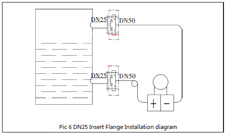
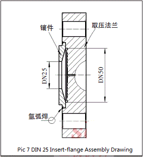
Figure 7 is the assembly drawing of the DN25 insert-flange assembly. The insert is embedded in the pressure-taking flange, and the connecting surface is argon arc welding ring-welded for one week to form the insert-flange assembly. When designing, pay attention to the calculation of the fitting size. There is a clearance fit between the two, and the fitting clearance is required to be between 0.05 and 0.15 mm to ensure the effectiveness of argon arc welding.
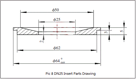
The inner cavity and outer dimensions of the insert are mainly considered in combination with the pressure-taking side of the pressure-taking flange, which is relatively easy to design. Because thin-walled parts are easily deformed during welding, the thickness and size design of inserts is a difficult design. In order to determine the size of the minimum thickness of the insert, through multiple welding tests, the results show that: when the total thickness of the insert is less than 4.5 mm, the sealing surface of the insert is seriously deformed after welding; when the total thickness of the insert is equal to 5 mm, the welding The surface of the sealing surface of the insert has almost no deformation, and the sealing effect is good through the pressing test. Therefore, the total thickness of the insert is selected as δ=5 mm, and considering the aesthetics of the design, it is designed as a stepped type as shown in Figure 8.
3 Comparative analysis
The transition flange does not change the design of the pressure-taking flange, but only supplements the installation design, which is close to the standardized design. Therefore, the advantages of using it are simple design and stable performance of the instrument, while the disadvantages are large volume and weight, high material and processing costs, large installation space, and the design changes when the nominal pressure of the flange changes. The adapter flange has a secondary design for the pressure-taking flange. At the same time, the adapter flange, short pipe, direct installation flange, and corresponding sealing rings, bolts and nuts need to be designed. There are many and complex parts, and the material and processing costs are relatively high. The advantage is that the flanges of different pressure levels of DN25 can be universally designed to realize the serialization of their specifications. The design of the insert-flange assembly is simple, and the design parts are few. It only needs to design the insert and change the pressure-taking flange to complete the design. The cost is low, but its weakness is that the overall performance of the instrument is slightly worse, especially the dead zone. Large, long-term use will cause residues in the gap between the pressure-taking flange and the insert, and even affect the response speed of the instrument.
Regarding the selection of the DN25 small diameter flange design scheme, it is generally necessary to communicate with the user and the design institute in the technical disclosure in the early stage of the project review, and determine it according to the on-site process conditions, the requirements for the performance indicators of the instrument and the actual needs of the user. The three schemes of transition flange, adapter flange and insert-flange can be reflected in the instrument selection, and remarks and emphasis should be added if necessary. Practice has proved that the adapter flange design is used to realize the conversion of DN50 to DN25 caliber. The performance of the remote transmitter is stable and reliable, and can fully meet the on-site process requirements. At the same time, the design can realize serialization of specifications, and the parts are highly versatile. To a certain extent It shortens the delivery time and reduces the manufacturing cost. It is recommended to choose this scheme first.
4 Conclusion
For the design of DN25 small diameter flange of FCX-AIII series remote transmitter, three methods are usually adopted: transition flange, adapter flange and insert-flange, which are supplementary designs on the basis of DN50 flange. , all three have their pros and cons. Which design method is selected mainly depends on the on-site process conditions, measurement range, installation location and other factors of the transmitter, and on the premise of meeting the user's requirements, and considering the serialization of design, standardization of production, standardization of process and low cost. The design ideas and methods proposed in this paper have promotion significance for the research and development of smaller diameter flanges such as FCX-AIII series remote transmitters DN20 and DN15.


